27 KiB
PVC Cluster Architecture considerations
- PVC Cluster Architecture considerations
This document contains considerations the administrator should make when preparing for and building a PVC cluster. It is important that prospective PVC administrators read this document thoroughly before deploying a cluster to ensure they understand the requirements, caveats, and important details about how PVC operates.
Node Specifications: Considering the size of nodes
PVC nodes, especially coordinator nodes, run a significant number of software applications in addition to the virtual machines (VMs). It is therefore extremely important to size the systems correctly for the expected workload while planning both for redundancy and future capacity. In general, taller nodes are better for performance, providing a more powerful cluster on fewer physical machines, though each workload may be different in this regard.
The following table provides bare-minimum, recommended, and optimal specifications for a cluster. The bare-minimum specification would be suitable for testing or a small lab, but not for production use. The recommended specification would be suitable for a small production cluster running lightweight VMs. The optimal cluster would be the ideal for running a demanding, resource-intensive production cluster. Note that these are the minimum resources required, and actual usage will likely require more resources than those presented here - this is mostly to show the minimums for each specified configuration (i.e. testing, light production, heavy production).
| Resource | Minimum | Recommended | Optimal |
|---|---|---|---|
| CPU generation | Intel Nehalem (2008) / AMD Bulldozer (2011) | Intel Sandy Bridge (2011) / AMD Naples (2017) | Intel Haswell (2013) / AMD Rome (2019) |
| CPU cores (per node) | 4x @1.8GHz | 8x @2.0GHz | 12x @2.2 GHz |
| RAM (per node) | 16GB | 48GB | 64GB |
| System disk (SSD/HDD/USB/SD/eMMC) | 1x 10GB | 2x 10GB RAID-1 | 2x 32GB RAID-1 |
| Data disk (SSD only) | 1x 200GB | 1x 400GB | 2x 400GB |
| Network interfaces | 1x 1Gbps | 2x 1Gbps LAG | 2x 10Gbps LAG |
| Total CPU cores (healthy) | 12x | 24x | 36x |
| Total CPU cores (n-1) | 8x | 16x | 24x |
| Total RAM (healthy) | 48GB | 144GB | 192GB |
| Total RAM (n-1) | 32GB | 96GB | 128GB |
| Total disk space | 200GB | 400GB | 800GB |
System Disks
The system disk(s) chosen are important to consider, especially for coordinators. Ideally, an SSD, or two SSDs in RAID-1/mirroring are recommended for system disks. This helps ensure optimal performance for the system (e.g. swap space) and PVC components such as databases as well as the Ceph caches.
It is possible to run PVC on slower disks, for instance HDDs, USB drives, SD cards, or eMMC flash. For hypervisor-only nodes this will be acceptable; however for coordinators be advised that the performance of some aspects of the system may suffer as a result, and the longevity of the storage media must be carefully considered. RAID-1/mirroring is strongly recommended for these storage media as well, especially on coordinator nodes.
n-1 Redundancy
Care should be taken to examine the "healthy" versus "n-1" total resource availability. Under normal operation, PVC will use all available resources and distribute VMs across all cluster nodes. However, during single-node failure or maintenance conditions, all VMs will be required to run on the remaining hypervisors. Thus, care should be taken during planning to ensure there is sufficient resources for the expected workload of the cluster.
The general rule for available resource capacity planning can be though of as "1/3 of the total disks space, 2/3 of the total RAM, 2/3 of the total CPUs" for a 3-node cluster.
For memory provisioning of VMs, PVC will warn the administrator, via a Degraded cluster state, if the "n-1" RAM quantity is exceeded by the total maximum allocation of all running VMs. This situation can be worked around with sufficient swap space on nodes to ensure there is overflow, however the warning cannot be overridden. If nodes are of mismatched sizes, the "n-1" RAM quantity is calculated by removing (one of) the largest node in the cluster and adding the remaining nodes' RAM counts together.
System Memory Utilization
By default, several components of PVC outside of VMs will have large memory allocations, most notably Ceph OSD processes and Zookeeper database processes. These processes should be considered when selecting the RAM allocation of nodes, and adjusted in the Ansible group_vars if lower defaults are required.
Ceph OSD processes
By default, PVC will allow several GB (up to 4-6GB) of RAM allocation per OSD to maximize the available cache space and hence disk performance. This can be lowered as far as 939MB should the administrator require due to a low RAM configuration, but no further due to Ceph limitations; therefore at least 1GB of memory per storage OSD is required even in the most limited case.
Zookeeper processes
By default, the Java heap and stack sizes are set to 256MB and 512MB respectively, yieliding a memory usage of 500+MB after serveral days or weeks of uptime. This can be lowered to 32M or less for lightly-used clusters should the administrator require due to a low RAM configuration.
Operating System and Architecture
As an underlying OS, only Debian GNU/Linux 10.x "Buster" or 11.x "Bullseye" is supported by PVC. This is the operating system installed by the PVC node installer and expected by the PVC Ansible configuration system. Ubuntu or other Debian-derived distributions may work, but are not officially supported. PVC also makes use of a custom repository to provide the PVC software and (for Debian Buster) an updated version of Ceph beyond what is available in the base operating system, and this is only compatible officially with Debian 10 or 11. PVC will generally be upgraded regularly to support new Debian versions. As a rule, using the current versions of the official node installer and Ansible repository is the preferred and only supported method for deploying PVC.
Currently, only the amd64 (Intel 64 or AMD64) architecture is officially supported by PVC. Given the cross-platform nature of Python and the various software components in Debian, it may work on armhf or arm64 systems as well, however this has not been tested by the author and is not officially supported at this time.
Storage Layout: Ceph and OSDs
PVC makes use of Ceph, a distributed, replicated, self-healing, and self-managing storage system to provide shared VM storage. While a PVC administrator is not required to understand Ceph for day-to-day administraton, and PVC provides interfaces to most of the common storage functions required to operate a cluster, at least some knowledge of Ceph is advisable.
The Ceph subsystem of PVC creates a "hyperconverged" cluster whereby storage and VM hypervisor functions are collocated onto the same physical servers; PVC does not differentiate between "storage" and "compute" nodes, and while storage support can be disabled and an external Ceph cluster used, this is not recommended. The performance of the storage must be taken into account when sizing the nodes as mentioned above.
Ceph on PVC is laid out similar to the other daemons. The Ceph Monitor and Manager functions are delegated to the Coordinators over the storage network, with all nodes connecting to these hosts to obtain the CRUSH maps and select OSD disks. OSDs are then distributed on all hosts, potentially including non-coordinator hypervisors if desired, and communicate with clients and each other over the storage network.
Disks must be balanced across all storage-containing nodes. For instance, adding 1 disk to 1 node is not sufficient to increase storage space; 1 disk must be added to all storage-containing nodes, based on the configured replication scheme of the various pools (see below), at the same time for the available space to increase. Ideally, disk sizes should also be identical across all storage disks, though the weight of each disk can be configured when added to the cluster. Generally speaking, fewer larger disks are preferable to many smaller disks to minimize storage resource utilization, however slightly more storage performance can be gained from using many small disks, if the other cluster hardware, and specifically CPUs, are performant enough. The administrator should therefore always aim to choose the biggest disks they can and grow by adding more identical disks as space or performance needs grow.
PVC Ceph pools make use of the replication mechanism of Ceph to store multiple copies of each object, thus ensuring that data is always available even when a host is unavailable. Only "replica"-based Ceph redundancy is supported by PVC; erasure coded pools are not supported due to major performance impacts related to rewrites and random I/O as well as management overhead.
The default replication level for a new pool is copies=3, mincopies=2. This will store 3 copies of each object, with a host-level failure domain, and will allow I/O as long as 2 copies are available. Thus, in a cluster of any size, all data is fully available even if a single host becomes unavailable. It will however use 3x the space for each piece of data stored, which must be considered when sizing the disk space for the cluster: a pool in this configuration, running on 3 nodes each with a single 400GB disk, will effectively have 400GB of total space available for use. As mentioned above, new disks must also be added in groups across nodes equal to the total number of copies to ensure new space is usable; for instance in a copies=3 scheme, at least 3 disks must thus be added to different hosts at the same time for the avilable space to grow.
Non-default values can also be set at pool creation time. For instance, one could create a copies=3, mincopies=1 pool, which would allow I/O with two hosts down, but leaves the cluster susceptible to a write hole should a disk fail in this state; this configuration is not recommended in most situations. Alternatively, for additional resilience, one could create a copies=4, mincopies=2 pool, which would also allow 2 hosts to fail, without a write hole, but would consume 4x the space for each piece of data stored and require new disks to be added in groups of 4 instead. Practically any combination of values is possible, however these 3 are the most relevant for most use-cases, and for most, especially small, clusters, the default is sufficient to provide solid redundancy and guard against host failures until the administrator can respond.
Replication levels cannot be changed within PVC once a pool is created, however they can be changed via manual Ceph commands on a coordinator should the administrator require this, though discussion of this process is outside of the scope of this documentation. The administrator should carefully consider sizing, failure domains, and performance when first selecting storage devices and creating pools, to ensure the right level of resiliency versus data usage for their use-case and planned cluster size.
Physical network considerations
At a minimum, a production PVC cluster should use at least two 1Gbps Ethernet interfaces, connected in an LACP or active-backup bond on one or more switches. On top of this bond, the various cluster networks should be configured as 802.3q vLANs. PVC is be able to support configurations without bonding or 802.1q vLAN support, using multiple physical interfaces and no bridged client networks, but this is strongly discouraged due to the added complexity this introduces; the switches chosen for the cluster should include these requirements as a minimum.
More advanced physical network layouts are also possible. For instance, one could have two isolated networks. On the first network, each node has two 10Gbps Ethernet interfaces, which are combined in a bond across two redundant switch fabrics and that handle the upstream and cluster networks. On the second network, each node has an additional two 10Gbps, which are also combined in a bond across the redundant switch fabrics and handle the storage network. This configuration could support up to 10Gbps of aggregate client traffic while also supporting 10Gbps of aggregate storage traffic. Even more complex network configurations are possible if the cluster requires such performance. See the Example Configurations section for some basic topology examples.
Only Ethernet networks are supported by PVC. More exotic interconnects such as Infiniband are not supported by default, and must be manually set up with Ethernet (e.g. EoIB) layers on top to be usable with PVC.
PVC manages the IP addressing of all nodes itself and creates the required addresses during node daemon startup; thus, the on-boot network configuration of each interface should be set to "manual" with no IP addresses configured. This can be ignored safely, however, and the addresses specified manually in the networking configurations. PVC nodes use a split (/etc/network/interfaces.d/<iface>) network configuration model.
Network Layout: Considering the required networks
A PVC cluster needs several different networks to operate properly; they are described in detail below and the administrator should ensure they account for all the required networks when planning the cluster.
PVC system networks
Upstream: Connecting the nodes to the wider world
The upstream network functions as the main upstream for the cluster nodes, providing Internet access and a way to route managed client network traffic out of the cluster. In most deployments, this should be an RFC1918 private subnet with an upstream router which can perform NAT translation and firewalling as required, both for the cluster nodes themselves, and also for any RFC1918 managed client networks.
The floating IP address in the cluster network can be used as a single point of communication with the active primary node, for instance to access the DNS aggregator instance or the management API. PVC provides only limited access control mechanisms to the API interface, so the upstream network should always be protected by a firewall; running PVC directly accessible on the Internet is strongly discouraged and may post a serious security risk, and all access should be restricted to the smallest possible set of remote systems.
Nodes in this network are generally assigned static IP addresses which are configured at node install time and in the Ansible deployment configuration.
The upstream router should be able to handle static routes to the PVC cluster, or form a BGP neighbour relationship with the coordinator nodes and/or floating IP address to learn routes to the managed client networks.
The upstream network should generally be large enough to contain:
- The upstream router(s)
- The nodes themselves
- In most deployments, the node IPMI management interfaces.
For example, for a 3+ node cluster, up to about 90 nodes, the following configuration might be used:
| Description | Address |
|---|---|
| Upstream network | 10.0.0.0/24 |
| Router VIP address | 10.0.0.1 |
| Router 1 address | 10.0.0.2 |
| Router 2 address | 10.0.0.3 |
| PVC floating address | 10.0.0.10 |
| node1 | 10.0.0.11 |
| node2 | 10.0.0.12 |
| etc. | etc. |
| node1-ipmi | 10.0.0.111 |
| node2-ipmi | 10.0.0.112 |
| etc. | etc. |
For even larger clusters, a /23 or even larger network may be used.
Cluster: Connecting the nodes with each other
The cluster network is an unrouted private network used by the PVC nodes to communicate with each other for database access and Libvirt migrations. It is also used as the underlying interface for the BGP EVPN VXLAN interfaces used by managed client networks.
The floating IP address in the cluster network can be used as a single point of communication with the active primary node.
Nodes in this network are generally assigned IPs automatically based on their node number (e.g. node1 at .1, node2 at .2, etc.). The network should be large enough to include all nodes sequentially.
Generally the cluster network should be completely separate from the upstream network, either a separate physical interface (or set of bonded interfaces) or a dedicated vLAN on an underlying physical device, but they can be collocated if required.
Storage: Connecting Ceph daemons with each other and with OSDs
The storage network is an unrouted private network used by the PVC node storage OSDs to communicated with each other, for Ceph management functionality, and for QEMU-to-Ceph disk access, without using the main cluster network and introducing potentially large amounts of traffic there.
The floating IP address in the storage network can be used as a single point of communication with the active primary node, though this will generally be of little use.
Nodes in this network are generally assigned IPs automatically based on their node number (e.g. node1 at .1, node2 at .2, etc.). The network should be large enough to include all nodes sequentially.
The administrator may choose to collocate the storage network on the same physical interface as the cluster network, or on a separate physical interface. This should be decided based on the size of the cluster and the perceived ratios of client network versus storage traffic. In large (>3 node) or storage-intensive clusters, this network should generally be a separate set of fast physical interfaces, separate from both the upstream and cluster networks, in order to maximize and isolate the storage bandwidth. If the administrator does choose to collocate these networks, they may also share the same IP address, thus eliminating any distinction between the Cluster and Storage networks. The PVC software handles this natively when the Cluster and Storage IPs of a node are identical.
PVC client networks
Bridged (unmanaged) Client Networks
The first type of client network is the unmanaged bridged network. These networks have a separate vLAN on the device underlying the other networks, which is created when the network is configured. VMs are then bridged into this vLAN.
With this client network type, PVC does no management of the network. This is left entirely to the administrator. It requires switch support and the configuration of the vLANs on the switchports of each node's physical interfaces before enabling the network.
Generally, the same physical network interface will underlay both the cluster networks as well as bridged client networks. PVC does however support specifying a separate physical device for bridged client networks, for instance to separate these networks onto a different physical interface from the main cluster networks.
VXLAN (managed) Client Networks
The second type of client network is the managed VXLAN network. These networks make use of BGP EVPN, managed by route reflection on the coordinators, to create virtual layer 2 Ethernet tunnels between all nodes in the cluster. VXLANs are then run on top of these virtual layer 2 tunnels, with the active primary PVC node providing routing, DHCP, and DNS functionality to the network via a single IP address.
With this client network type, PVC is in full control of the network. No vLAN configuration is required on the switchports of each node's physical interfaces, as the virtual layer 2 tunnel travels over the cluster layer 3 network. All client network traffic destined for outside the network will exit via the upstream network interface of the active primary coordinator node.
NOTE: These networks may introduce a bottleneck and tromboning if there is a large amount of external and/or inter-network traffic on the cluster. The administrator should consider this carefully when deciding whether to use managed or bridged networks and properly evaluate the inter-network traffic requirements.
Other Client Networks
Future PVC versions may support other client network types, such as direct-routing between VMs.
Node Layout: Considering how nodes are laid out
A production-grade PVC cluster requires at least 3 nodes running the PVC Daemon software. 1-node clusters are supported for very small clusters, home labs, and testing, but provide no redundancy; they should not be used in production situations.
Node Functions: Coordinators versus Hypervisors
Within PVC, a given node can have one of two main functions: "Coordinator" or "Hypervisor".
Coordinators
Coordinators are a special set of 3 or 5 nodes with additional functionality. The coordinator nodes run, in addition to the PVC software itself, a number of databases and additional functions which are required by the whole cluster. An odd number of coordinators is always required to maintain quorum, though there are diminishing returns when creating more than 3. These additional functions are:
- The Zookeeper database cluster containing the cluster state and configuration
- The Patroni PostgreSQL database cluster containing DNS records for managed networks and provisioning configurations
- The FRR EBGP route reflectors and upstream BGP peers
In addition to these functions, coordinators can usually also run all other PVC node functions.
The set of coordinator nodes is generally configured at cluster bootstrap, initially with 3 nodes, which are then bootstrapped together to form a basic 3-node cluster. Additional nodes, either as coordinators or as hypervisors, can then be added to the running cluster to bring it up to its final size, either immediately or as the needs of the cluster change.
The Primary Coordinator
Within the set of coordinators, a single primary coordinator is elected at cluster startup and as nodes start and stop, or in response to administrative commands. Once a node becomes primary, it will remain so until it stops or is told not to be. This coordinator is responsible for some additional functionality in addition to the other coordinators. These additional functions are:
- The floating IPs in the main networks
- The default gateway IP for each managed client network
- The DNSMasq instance handling DHCP and DNS for each managed client network
- The API and provisioner clients and workers
PVC gracefully handles transitioning primary coordinator state, to minimize downtime. Workers will continue to operate on the old coordinator if available after a switchover and the administrator should be aware of any active tasks before switching the active primary coordinator.
Hypervisors
Hypervisors consist of all other PVC nodes in the cluster. For small clusters (3 nodes), there will generally not be any non-coordinator nodes, though adding a 4th would require it to be a hypervisor to preserve quorum between the coordinators. Larger clusters should generally add new nodes as Hypervisors rather than coordinators to preserve the small set of coordinator nodes previously mentioned.
Geographic redundancy
PVC supports geographic redundancy of nodes in order to facilitate disaster recovery scenarios when uptime is critical. Functionally, PVC behaves the same regardless of whether the 3 or more coordinators are in the same physical location, or remote physical locations.
When using geographic redundancy, there are several caveats to keep in mind:
-
The Ceph storage subsystem is latency-sensitive. With the default replication configuration, at least 2 writes must succeed for the write to return a success, so the total write latency of a write on any system will be equal to the maximum latency between any two nodes. It is recommended to keep all PVC nodes as "close" as possible latency-wise or storage performance may suffer.
-
The inter-node PVC networks must be layer-2 networks (broadcast domains). These networks must be spanned to all nodes in all locations.
-
The number of sites and positioning of coordinators at those sites is important. A majority (at least 2 in a 3-coordinator cluster, or 3 in a 5-coordinator) of coordinators must be able to reach each other in a failure scenario for the cluster as a whole to remain functional. Thus, configurations such as 2 + 1 or 3 + 2 splits across 2 sites do not provide full redundancy, and the whole cluster will be down if the majority site is down. It is thus recommended to always have an odd number of sites to match the odd number of coordinators, for instance a 1 + 1 + 1 or 2 + 2 + 1 configuration. Also note that all hypervisors much be able to reach the majority coordinator group or their storage will be impacted as well.
-
Even if the PVC software itself is in an unmanageable state, VMs will continue to run if at all possible. However, since the storage subsystem makes use of the same quorum, losing more than half of the nodes will very likely result in storage interruption as well, which will affect running VMs.
If these requirements cannot be fulfilled, it may be best to have separate PVC clusters at each site and handle service redundancy at a higher layer to avoid a major disruption.
Example Configurations
This section provides diagrams of 3 possible node configurations. These diagrams can be extrapolated out to almost any possible configuration and number of nodes.
Basic 3-node cluster
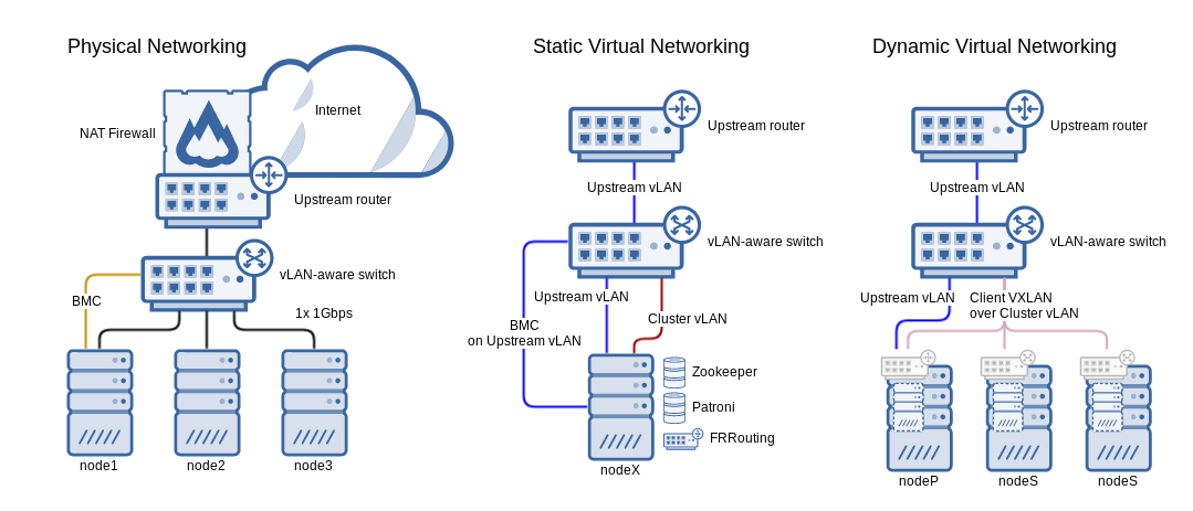
Above: A diagram of a simple 3-node cluster; all nodes are coordinators, single 1Gbps network interface per node, collapsed cluster and storage networks
Mid-sized 8-node cluster with 3 coordinators
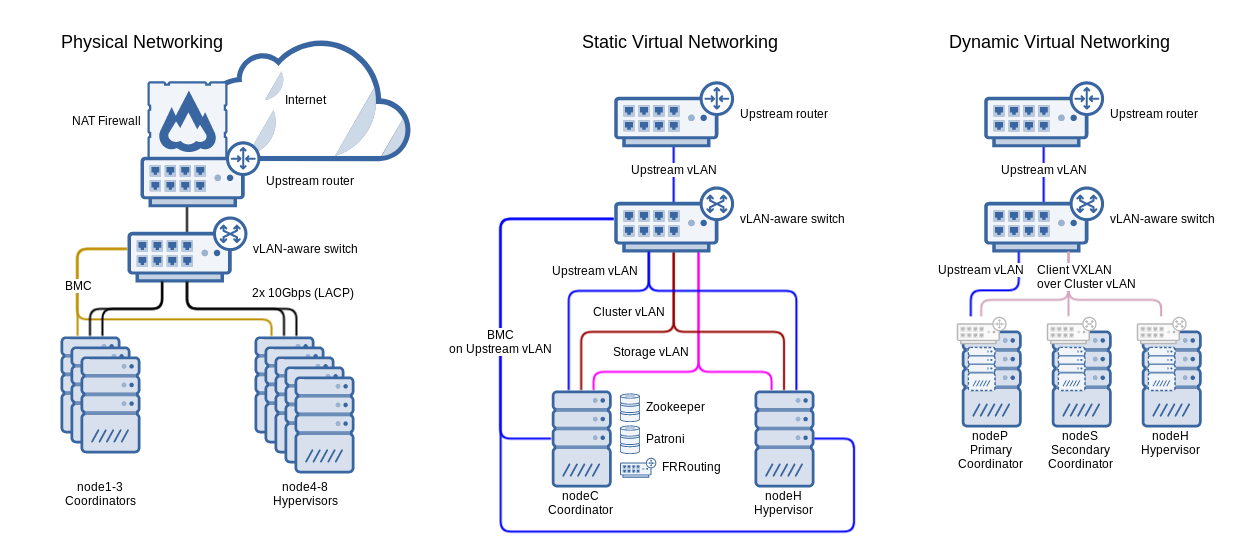
Above: A diagram of a mid-sized 8-node cluster with 3 coordinators, dual bonded 10Gbps network interfaces per node
Large 17-node cluster with 5 coordinators
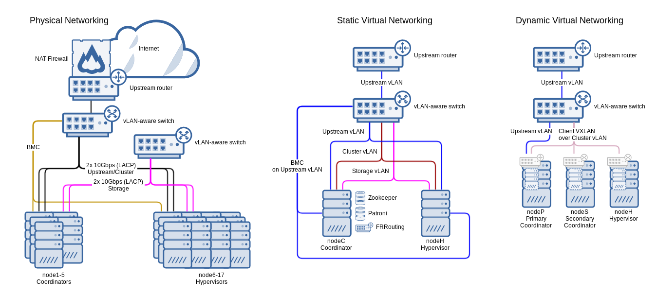
Above: A diagram of a large 17-node cluster with 5 coordinators, dual bonded 10Gbps network interfaces per node for both cluster/upstream and storage networks